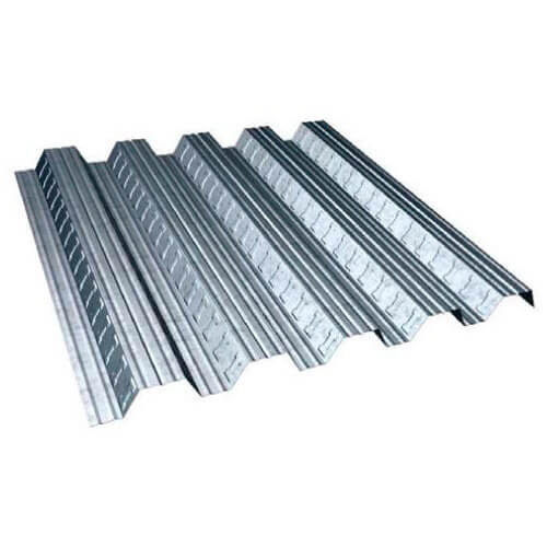
Steel Decking Sheets (50 MM)

Trapezoidal Metal Profile sheets with strong and reliable shear bond performance which is augmented by cross embossing located in the profile. The composite floor profile offers the ultimate in the light weight steel decking which reduced concrete usage to provide a cost effective and alternative floor solution that easy to install.
Application
- High Rise Buildings
- Multiplexes / Commercial Buildings
- Power Plant Buildings
- Office Buildings
- Mezzanine Floors in Industrial Buildings & Warehouses
- Steel deck fo rmezanine floors
Technical Specification
Base Metal
- High tensile structural grade steel
- Coating Mass 120, 180 & 275 GSM
- Coating Standard IS : 277
- Yield Strength 240 MPA
- Thickness
- 0.8mm/1mm/1.2mm/1.6mm
- Available Finish
- Cold Rolled (CR) l Galvanised l Both side primer coated (Galvanised)
- Pre coated galvanised under side giving durable and attractive appearance and minimum future maintenance.
Advantages
- Reduced Concrete usage: Tensile steel for composite slab construction that cuts down on slab thickness and dead weight of buildings. Providing a more sustainable solution and reducing costs.
- No separate formwork required for slab casting.
- Reduces construction time.
- Technical department at Alfa offers comprahas sive advisory of service on design of composite flooring should quiries arise which are not cover by this literature please contact us.
Load Tables
The structural adequacy of DECK sections is established by choosing the section to provide requisite sectional modules to satisfy moment and deflection criterion. A moment coefficient of 1/8 is used for single and dual spans and 1/10 for 3 or more spans. The deflection co-efficient are 0.013 for single span and 0.0078 for multi spans. The maximum deflection of the DECKSHEETS is restricted to L/250 under uniformly distributed loads.
Steel Decking Sheets
Composite Decking Sheet
In our Composite Decking Sheet the floor is constituted by a profiled Deck sheet made of metal onto which a layer of concrete is poured. The GI decking sheet is attached to the concrete by method for mouldings on the sheet which prevent the cement from slipping on a level plane and disconnecting vertically. At the point when the concrete is spilled and until it has arrived at a proper level of solidifying, the weights of the concrete, staff working and supplies utilized as a part of borne by the sheet alone. When the cement has solidified the sheet and the concrete structure a bound together bond.
Non-Composite Decking Sheet
Permanent Formwork Profile Range
We manufacture profiles which are used as permanent formwork. Permanent formwork remains it situ for the life of the building but, unlike composite flooring profiles, it does not Act as reinforcement in the concrete slab.
- The steel decking supports the wet concrete and construction loads.
- Temporary propping can be eliminated.
- The concrete slab requires full structural bar or mesh reinforcement.
Comparison Chart Of Decking Sheet
ALFA75 DATA SHEET
| 305/915 profile steel panel/345Mpa | ||||||
|---|---|---|---|---|---|---|
| Panel Thickness mm | Weight kg/m2 | Area cm2 | Ix cm4 | ZX-Top cm3 | ZX-Bottom cm3 | Ma Kn.m |
| mm | mm | kg.m2 | cm2 | mm | cm4 | |
| 0.80 | 8.57 | 9.76 | 100.90 | 26.91 | 26.91 | 5.570 |
| 1.00 | 10.71 | 12.19 | 126.10 | 33.63 | 33.63 | 6.961 |
| 1.20 | 12.84 | 15.25 | 157.70 | 42.05 | 42.05 | 8.705 |
| fy= | 34.5 | Kn/cm2 | ||||
| E= | 2.00E+08 | KN/M2 | ||||
| Slab depth(mm) | Volume of concrete (m3/m2) | weight of concrete | ||||
|---|---|---|---|---|---|---|
| Wet(kN/m2) | Dry(kN/m2) | |||||
| 100 | 0.063 | 1.51 | 1.48 | |||
| 150 | 0.113 | 2.71 | 2.66 | |||
| 200 | 0.163 | 3.91 | 3.83 | |||
| 250 | 0.213 | 5.11 | 5.01 | |||
| ALFA75 | Load span Tables | |||||
|---|---|---|---|---|---|---|
| Maximum span (double span) (in meters) | ||||||
| Panel Thickness | Profile Weight | Sectional Area | Concrete slab depth above profile | |||
| mm | kg/m2 | cm2 | 100mm | 150mm | 200mm | 250mm |
| 0.80 | 7.66 | 9.76 | 3.60 | 3.00 | 2.70 | 2.400 |
| 1.00 | 9.57 | 12.19 | 3.90 | 3.30 | 3.00 | 2.700 |
| 1.20 | 11.97 | 15.25 | 4.30 | 3.70 | 3.30 | 3.000 |
75/305
| DEPTH | 75 MM |
|---|---|
| PITCH | 305 MM |
| OVERALL | 922 MM |
| COVERED | 915 MM |
| THICKNESS | 0.8-1.2 MM |
| SPAN UPTO | UPTO 2 MTR (STEEL CONSUMPTION SAVED) |
PROPERTIES
|
305/941 profile steel panel/250Mpa (75mm rib) |
||||||
|
Panel Thickness mm |
Weight kg/m2 |
Area cm2 |
Ix cm4 |
ZX-Top cm3 |
ZX-Bottom cm3 |
Ma Kn.m |
|
0.80 |
5.94 |
7.57 |
38.79 |
12.68 |
19.01 |
1.901 |
|
1.00 |
7.43 |
9.46 |
48.49 |
15.79 |
23.89 |
2.369 |
|
1.20 |
8.91 |
11.35 |
58.19 |
18.89 |
28.81 |
2.834 |
| fy = 25 Kn/cm2 E = 2.00E+08 KN/M2 |
||||||
ALLOWABLE LOAD
|
Allowable load in (KN/m2) for deck 75mm (250Mpa) |
||||||||
|
Thickness |
Span In Meters |
|||||||
|
1 |
1.25 |
1.5 |
1.75 |
2 |
2.25 |
2.5 |
3 |
|
|
0.8 |
31.6 |
20.6 |
14.1 |
10.1 |
7.6 |
6.1 |
5.1 |
3.1 |
|
1 |
40.1 |
25.6 |
17.6 |
13.1 |
9.6 |
7.6 |
6.1 |
4.1 |
|
1.2 |
50.1 |
32.1 |
22.1 |
16.1 |
12.6 |
9.6 |
7.6 |
5.6 |
TR60+Load Span Tables (Normal Weight Concrete)-Steel Grade S350
Maximum spans(m) using normal weight concrete (wet density 2000 kg/m3) for S350 grade steel
Design Table Limits – Criteria
Typically spans are governed by the maximum “un-propped” condition at construction stage, except where values are for propped spans and are indicated as follows: Spans shown in red indicate where spans are limited by the fire condition, greater spans may be achievable by either increasing mesh size or addition of bottom reinforcement. Spans shown in the blue indicate where spans are limited by the composite/normal stage conditions, greater spans may be achievable where share studs are provided.

